In solids handling processes screws are often used to feed powders from silos. This has a number of advantages: contamination of powder is avoided, as well as pollution of the surroundings. A proper feed rate can be achieved in a large range of feed capacity. When using a screw feeder, the hopper of the silo can be wedge shaped. This offers an additional advantage with regard tp flow. However, if a screw feeder is not designed properly, core flow and bridging can occur. Also the risk of flooding (uncontrollable flow) or excessive wear is present. A proper design, where pitch and core diameter are adjusted to the properties of the product, prevents these problems.

Desired flow pattern during feeding
Introduction
In a production process solids will be handled at one point or another. Raw materials are often in the form of solids, and also at processes with mainly liquids or gasses, there usually are steps where powders are used. The feeding of these components is of great importance. Too much or too little causes a bad quality of the final product. Even if it concerns a cheap filler, stagnation of over-feeding can lead to high cost if the process is disturbed. The silo in which the powder is stored and the feeding device therefore deserves the proper attention.
In the silo mass flow is desired (see the article Silo design), because core flow has disadvantages in relation to flow, ageing and degradation of the product. Evidently also bridging must be avoided. Powders fed to a process are often very fine and adhesive, because they have a large specific area or an open particle structure to improve reactivity.
In most cases this means that the powder has poor flow properties. Because of this it is best to use a wedge shaped hopper (a hopper with two vertical walls). This type of hopper is better than a round or square hopper in regard to flow pattern and bridging.
However, a wegde shaped hopper means that the opening is slot shaped. It is of great importance that the powder is withdrawn over the full length of the opening. See the figures for a schematic presentation. A screw feeder can be made to achieve this.

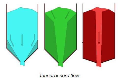
Undesired flow pattern caused by feeder
Screw Feeder
A screw feeder is mounted directly under the opening of a hopper. The product in the silo therefore rests on a part of the screw, and the screw flights are filled completely. This is a clear difference with a transport screw, where the product is fed with a capacity that is smaller than the capacity of the screw. In that case the screw is never filled for a 100%.
A screw feeder is used a lot for the feeding of powders from a (wedge shaped) hopper. The reasons for this are:
- even withdrawal of the powder is well possible, resulting in mass flow.
- the screw is closed, so there is no risk of pollution of the powder or surroundings.
- proper feeding is possible, in a broad range of capacity.
- the life of the screw; a wear resistant type is possible.
- the screw can be made well resistant against for example high temperature, aggressive environment, etc.
Working Principle
The following example illustrates how transport in a screw is achieved. Imagine standing on spiral stairs, on a certain step. If the stairs are rotated, you will rotate with the stairs at the level you are standing. When leaning against the circular wall around the stairs, the situation changes. There are two possibilities:
1) You stay at the same step - the wall will rub against you.
2) You go up a step, and stay at the same position at the wall, only slightly higher.
At option 2 you will rub against the wall in vertical direction. It depends on the height of the steps what the way of the least resistance is.
For a screw this means that transport depends on the friction between product and 1) screw blade, 2) trough or tube and 3) product itself (in the part beneath the silo). The height of the steps compares to the blade angle, formed by the pitch and the screw diameter. Furthermore the core diameter is of importance, because this determines the content of a pitch.

Capacity profile of a screw feeder
Pitch vs capacity
In the capacity profile above of a screw feeder there are 3 characteristic points:
1) the minimum pitch. Below this pitch no transport occurs.
2) the pitch where optimum transport occurs. Below this pitch not all product is moving yet.
3) the maximum pitch. The pitch is so large now, that a further increase will affect the capacity in a negative way.
The position of these points depend on core diameter, screw diameter and product characteristics.
1) Minimum pitch
When the pitch is smaller than the minimum pitch, the product will be jammed between the blades, and it rotates with the screw. Here the core diameter plays an important role. If this diameter is bigger, the surface of the blade is smaller, resulting in a smaller minimum pitch.
Also the wall friction and the internal friction are of importance. In table 1 values of the minimum pitch (lower boundary) are calculated. The friction between product and trough and product and screw blade is supposed to be equal. In the area between the lower boundary (1) and upper boundary (2) of the minimum pitch the effectiveness of transport is expressed in factor Z (see darkblue line in figure Capacity profile).

Values for the minimum screw pitch
2) Optimum pitch
Above this pitch the functioning of the screw is best. In the table above this pitch is called the upper boundary of the minimum pitch. Just as the lower boundary the optimum pitch depends on the screw dimensions and the product characteristics. For a pitch above the optimum pitch the capacity increases almost linearly with the pitch. This is the area that is used for the design. When the pitch gets bigger, the capacity increase is less. At a certain point the capacity increase is so small that further increase of the pitch is not favourable.
3) Maximum pitch
Above this pitch the capacity decreases. The screw blade slips beneath the product. In a screw a pitch greater than the maximum pitch may not be present, because this leads to jamming of the screw. The power needed shoots up and if the drive is not damaged, severe damage of the screw will result.
Screw feeder design
At the design of a screw feeder the goal is to let the capacity increase evenly over the length of the screw. The design procedure is as follows:
- the wall friction of the product on trough and screw blade and the internal friction of the product is measured.
- the capacity profile around the maximum pitch is calculated. On the basis of this value the maximum applicable pitch is fixed.
- the desired capacity and this pitch now determine: number of revolutions, screw diameter and core diameter at the discharge.
- The increase of the capacity per length of screw is fixed now. The filling in of core diameter and pitch can start.
- The core diameter at the start of the screw is chosen. For short screws this may be the same as the diameter at the discharge, but mostly a bigger core has to be chosen. The minimum pitch is calculated.
- The starting value of factor Z is chosen, in combination with the ’stickiness’ of the product. The resulting step in capacity can be smoothened with an extra blade with the starting pitch.
- The pitch increases until optimum transport is reached.
- If the core diameter at the start is bigger than at the end, the reduction of the core is determined.
- In the last part the pitch increases again, until the earlier determined value of the maximum applicable pitch is reached.
- In the transport section of the screw (after the bunker) the pitch increases slightly, to reduce the filling degree, and avoid jamming.
The result of this procedure is an equal withdrawal of the product over the length of the screw. See fig.4, in this figure also the capacity profile for a screw with a stepped pitch is given. With a well designed screw there will be no stagnant areas in the silo and the risk of bridging and flooding is reduced to a minimum.

Influence of screw pitch on flow in bunker
Power required
On the basis of the dimensions of the screw, the pitch profile and the product characteristics the torque and power needed can be determined. Here the difference between a screw feeder and a transport screw becomes evident. Through the higher filling degree of the screw (beneath the silo 100%, after that at least 80%) and because of the pressure of the product in the silo on the product in the screw, the torque and power needed is much higher than for a transport screw. In selection of a drive this is very important.
The start-up torque can be estimated on the basis of the silo pressure. It needs to be investigated if the motor, reductor and frequency regulator can yield this torque. See table below for an example.

Screw feeder drive power required